Pinout
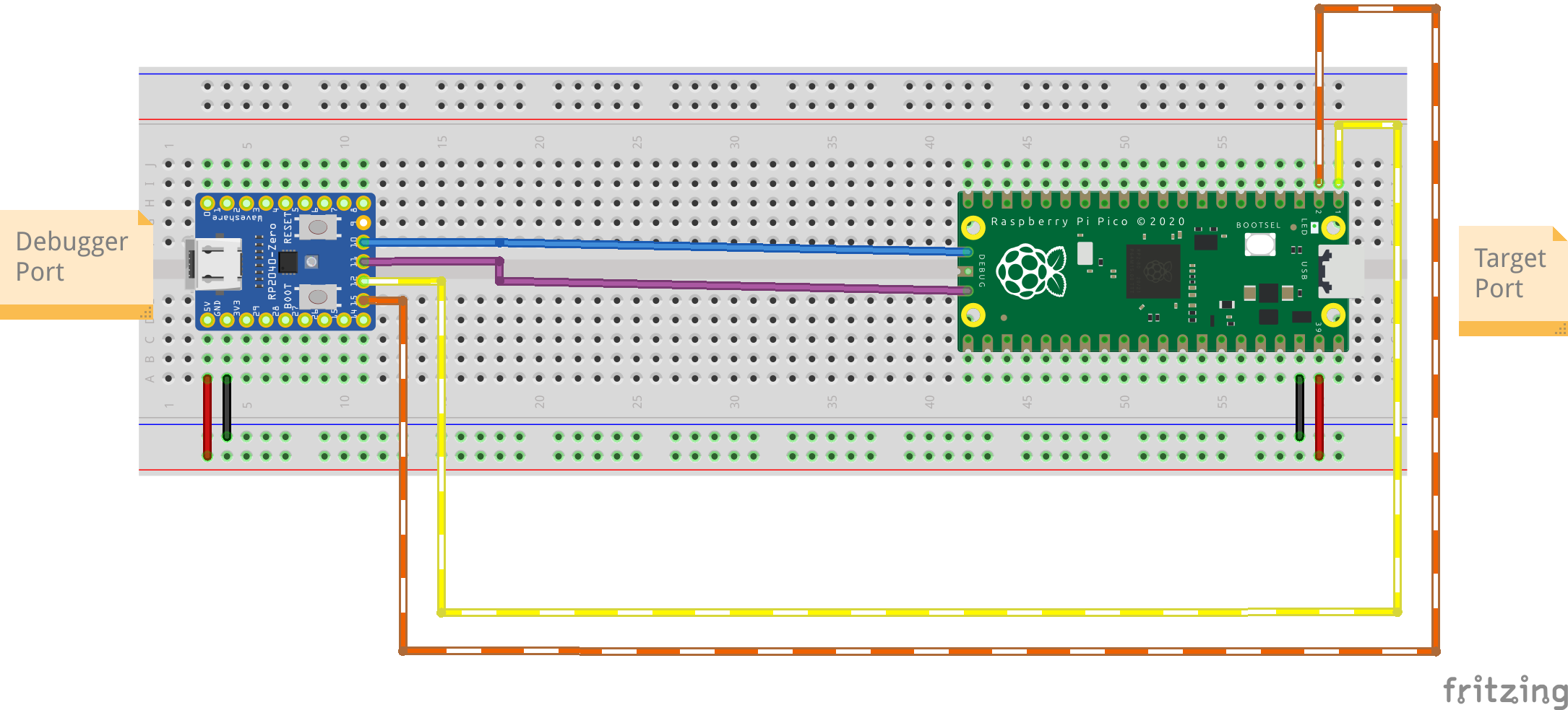
Check the RPi Pico Pinout Labels
| Zero Pin | Debugger Function | <-> | Pico Pin | Target Function | Notes |
|---|---|---|---|---|---|
| 9 | N/A | ||||
| 10 | SWCLK | CLK | SWCLK | ||
| 11 | SWDIO | DIO | SWDIO | ||
| 12 | UART0 TX | 1 | UART RX | 1 | |
| 13 | UART0 RX | 0 | UART TX | 1 |
How to use
-
Download the UF2 firmware from the Release page.
-
Flash it on the RP2040-Zero:
-
With the USB cable disconnected
-
Keep pressed the BOOT button
-
Connect the USB cable
-
An external memory device will appear
-
Drag and drop the
zephyr.uf2file downloaded before
-
-
Connect the two boards as shown above
-
[OPTIONAL] Test with
pyOCD-
Install with
sudo apt install python3-pyocd -
Check the device with:
pyocd list
$ pyocd list # Probe/Board Unique ID Target ---------------------------------------------------------------------- 0 Zephyr Project Zeroprobe CMSIS-DAP xxxxxxxxxxxxxxxx n/a -
-
[OPTIONAL] Test with
probe-rs$ probe-rs list The following debug probes were found: [0]: Zeroprobe CMSIS-DAP -- 2fe3:2ef0-4:xxxxxxxxxxxxxxxx (CMSIS-DAP) $ probe-rs benchmark --chip RP2040 --address 0x20000000 Probe: Probe type CMSIS-DAP V2 IF: 4 DESC: Some(InterfaceAltSetting { interface_number: 4, alternate_setting: 0, num_endpoints: 2, class: 255, subclass: 0,protocol: 0, string_index: Some(7), endpoints: [Endpoint { address: 0x03, direction: Out, transfer_type: Bulk, max_packet_size: 64, packets_per_microframe:1, interval: 0 }, Endpoint { address: 0x85, direction: In, transfer_type: Bulk, max_packet_size: 64, packets_per_microframe: 1, interval: 0 }] }), debug interface not specified, target chip RP2040 Test: Speed 3000, Word size 32bit, Data length 4 bytes, Number of iterations 5 Results: Read: 3779.65 bytes/s Std Dev 281.00, Write: 802960.41 bytes/s Std Dev 702031.03 Test: Speed 3000, Word size 32bit, Data length 32 bytes, Number of iterations 5 Results: Read: 13977.55 bytes/s Std Dev 2158.35, Write: 14192.47 bytes/s Std Dev 680.97 Test: Speed 3000, Word size 32bit, Data length 128 bytes, Number of iterations 5 Results: Read: 21714.88 bytes/s Std Dev 98.92, Write: 21079.25 bytes/s Std Dev 180.72 Test: Speed 3000, Word size 32bit, Data length 2048 bytes, Number of iterations 5 Results: Read: 24615.24 bytes/s Std Dev 170.70, Write: 24802.63 bytes/s Std Dev 119.16 Test: Speed 3000, Word size 32bit, Data length 32768 bytes, Number of iterations 5 Results: Read: 25305.23 bytes/s Std Dev 66.51, Write: 24417.86 bytes/s Std Dev 156.50
SWD/DAP
This should be automatically detected by your SDK if it uses openOCD/pyOCD/probe-rs.
TTY
On Linux this will expose two serial ports: one reporting the logs of the debugger, and one forwarding the target UART.
Assuming you don’t have anything else connected and that you have tio installed:
$ ls /dev
# this will show all the devices connected, we are interested in:
# ttyACM0 = UART bridge
# ttyACM1 = zeroprobe logs
$ tio /dev/ttyACM0
LED Colors
The RGB LED on the RP2040-Zero shows the state of the USB connection:
| Color | Meaning |
|---|---|
| Off | No power, the firmware is not running, or the board is in BOOT mode |
| Red | Powered and running, but not configured by a USB host |
| Blue | Configured by the host and ready, no USB traffic |
| Green | USB traffic in the last 0.5 s, on the debugger or on a serial port |
-
Red is shown at boot and after a USB reset. If it stays red while connected to a computer, the host did not set up the device: check that the cable supports data (not charge-only) and see Fixes.
-
Blue means the probe is ready to use.
-
Green turns on whenever the host and the probe exchange data: a debugger session (pyOCD, OpenOCD, probe-rs), or data on one of the two serial ports. It returns to blue after 0.5 s without traffic, so it flickers between green and blue with intermittent traffic and stays green while a debugger is polling. The debugger on the host generates traffic with the probe even with no target attached.
The colors and the timeout can be changed, see Configure.
Fixes
In case of device not detected:
- Check with lsusb:
$ lsusb -d 2fe3: Bus 005 Device 005: ID 2fe3:2ef0 NordicSemiconductor Zeroprobe CMSIS-DAP -
Add the udev rules for OpenOCD
-
sudo nano /etc/dev/rules.d/60-openocd.rules -
Copy the content of this file
-
sudo udevadm control --reload
-
TODO
- Use the addressable RGB LED to display information
Build
Requisites:
-
Zephyr SDK 1.0.1
-
Zephyr 4.4
-
Python 3.12 or newer, git, CMake, Ninja and the other Zephyr host dependencies
Set up the workspace
Zeroprobe is a west
manifest repository: west.yml pins Zephyr and the modules it needs
(cmsis_6 and hal_rpi_pico), so a single west init creates the whole
workspace.
$ python3 -m venv zeroprobe-ws/.venv
$ source zeroprobe-ws/.venv/bin/activate
$ pip install west

$ west init -m https://github.com/icpmoles/zeroprobe zeroprobe-ws
$ cd zeroprobe-ws
$ west update
$ west packages pip --install
$ west sdk install -t arm-zephyr-eabi
This creates the following layout, the same one used by the CI:
zeroprobe-ws/
├── .venv/        # Python virtual environment with west
├── .west/        # workspace config, created by west init
├── external/     # Zephyr and modules, fetched by west update
└── zeroprobe/    # this repository
If you already cloned the repository, run west init -l zeroprobe from its
parent directory instead of west init -m ..., then continue with
west update.
To build a branch other than main, add --mr <branch> to west init -m.
Compile
The board (rp2040_zero/rp2040) is already selected in CMakeLists.txt:
$ cd zeroprobe
$ west build
The firmware is written to build/zephyr/zephyr.uf2, flash it as described in
How to use, or run west flash --runner=uf2 while the board is in BOOT mode.
Use west build -p for a pristine build, e.g. after changing west.yml or
switching branch.
Configure
Options can be changed in prj.conf, in boards/rp2040_zero.conf, or
interactively with west build -t menuconfig.
The status LED is set in boards/rp2040_zero.conf:
| Option | Default | Meaning |
|---|---|---|
CONFIG_APP_LED_COLOR_UNCONFIGURED |
0x200000 |
Not configured by a USB host (red) |
CONFIG_APP_LED_COLOR_CONFIGURED |
0x000020 |
Configured by the host, no traffic (blue) |
CONFIG_APP_LED_COLOR_ACTIVE |
0x002000 |
USB traffic (green) |
CONFIG_APP_LED_IDLE_TIMEOUT_MS |
500 |
Idle time before going back to configured |
Colors are 0xRRGGBB, keep the values low: the WS2812 is very bright.
The colors and the timeout can also be changed at runtime from the shell on the logs serial port (see TTY), without rebuilding:
uart:~$ led show
unconfigured 0x200000
configured   0x000020 (current)
active       0x002000
timeout      500 ms
uart:~$ led set configured 0x100010
uart:~$ led timeout 1000
uart:~$ led save
| Command | Effect |
|---|---|
led show |
Show the settings, and which color is currently shown |
led set <unconfigured\|configured\|active> <RRGGBB> |
Change a color until the next reboot |
led timeout [ms] |
Show or change the idle timeout (1 to 60000 ms) |
led save |
Save the settings to flash, they are loaded at boot |
led reset |
Erase the saved settings and go back to the defaults |
Saved settings are kept in the last 4 KB sector of the flash, which is not touched when flashing a new UF2 firmware.
Credits
-
Images created with Fritzing
-
Boards footprint created by Vanepp: RP2040-Zero & RPi Pico
-
Favicon from “Noto Emoji Font”